Barber chair recline clearance is the space needed for the complete chair to move and for the practitioner to work around the client in the intended positions. The upright footprint is only the starting point. Headrest extension, a synchronized footrest, rotation, adjacent equipment, and access to controls can all set the final station size.
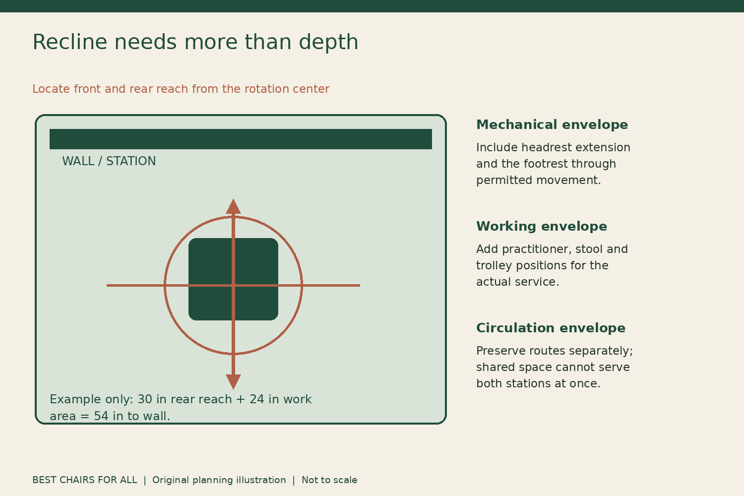
Do not buy a reclining chair from a single overall-depth number. Request its dimension drawing, identify the rotation center, and mark the front and rear reach of each intended configuration. Then rehearse the service around that outline. A chair can mechanically clear a wall while leaving too little room for the person providing the service.
Start with an exact configuration
Record the manufacturer, chair model, base, headrest, footrest, heelrest, and any extended leg support. Keep regional product documents consistent. A model sold in several markets may have different bases or accessories, and an older brochure may not describe the version currently quoted.
The Takara Belmont Apollo 2 configuration and depth specifications lists a depth range of 940–1380 mm with the specified SP-RH2 hydraulic base and describes synchronized backrest and footrest movement. The manufacturer also notes that dimensions can change with another base. Those figures describe that product configuration, not a general minimum room depth for barber chairs.
Minerva's Minerva Figaro upright and reclined footprint lists its Figaro at 43.5 inches deep upright and 62 inches reclined, with a 28-inch overall width. These are useful comparison facts, but they still do not tell you how much of the added depth falls behind the rotation center. Obtain the drawing or a supplier measurement before deciding where the base belongs.
Understand depth versus rearward travel
Overall depth measures from the farthest rear point to the farthest front point in a stated position. It does not necessarily locate either point relative to the base. When a backrest reclines and a legrest rises, both ends can contribute to the total increase. Assigning all of that increase behind the seat is an unsupported assumption.
Similarly, half the overall length is not automatically the rearward radius. Many chairs are not centered symmetrically around their base. A long footrest may project farther forward than the headrest projects backward, or the reverse may occur in a particular position. Use dimensions from the rotation center whenever possible.
If the drawing lacks those measurements, ask the supplier to provide them for upright, fully reclined, and extended-headrest positions. State the height setting used for the measurement. Do not convert a vague salesperson estimate into a permanent installation dimension without confirmation, particularly for a floor-mounted base.
Map three overlapping envelopes
The mechanical envelope contains the chair's parts through intended movement. The working envelope adds the practitioner, stool, trolley, and tools used in the service. The circulation envelope preserves the route through the room and access to doors or other facilities. Keep these distinct on the plan so one is not accidentally counted as another.
A chair may stay within its mechanical envelope while a practitioner steps into the circulation route to reach the client's head. That is a workflow conflict. A trolley may fit beside an upright chair but occupy the footrest's movement path when the seat rotates. That is a movement conflict. Both deserve resolution before the station is booked.
Use different tape colors or different line styles on a scaled drawing. Label which boundaries come from manufacturer documents, which are measured at the site, and which are your own proposed working allowances. This prevents a personal preference from being mistaken for a manufacturer requirement or a local building rule.
The pivot-center worksheet
Mark a point called O for the rotation center. Record the farthest rear reach R and front reach F from O in each intended position. Add the widest side reach, including levers and accessories. Record the source of every dimension and whether it includes the headrest at its usable extension.
Now add the proposed practitioner space behind and beside those positions. Do not use a universal allowance from an unrelated shop diagram. Rehearse your own techniques, including head positioning, cape handling, and access to the recline controls. Note whether you stand or use a stool for each part of the service.
Finally, record the nearest fixed obstacles in each direction: wall, mirror cabinet, radiator, door, shelf, or another chair's envelope. Measure from O to those obstacles. The worksheet should show the limiting condition clearly, such as “reclined headrest plus operator position behind seat,” rather than a single unexplained station-depth total.
Worked calculation with hypothetical dimensions
Suppose a hypothetical chair drawing gives 30 inches rearward and 34 inches forward from O when fully reclined with the headrest in the intended position. Overall depth is 64 inches. If your measured service rehearsal needs another 24 inches behind the headrest, the proposed wall-to-center distance becomes 54 inches: 30 plus 24.
That 24-inch working allowance is an example chosen for this exercise, not an industry standard or code minimum. A different practitioner, stool, service, or access requirement could need more. If a cabinet projects four inches from the wall, measure from its face or add the projection explicitly; otherwise the useful space is four inches smaller than the drawing suggests.
At the front, compare the 34-inch reach with the trolley and circulation plan. Do not assume unused space behind the chair compensates for a blocked route in front. Each direction has its own constraints. This simple arithmetic becomes reliable only when the chair's front and rear dimensions are known separately.
Rotation changes the limiting direction
A reclining chair that fits parallel to a wall may require more width when turned. For a simplified planning model, a point located R inches from the rotation center sweeps a circle of radius R. The actual chair includes multiple points and shapes, but the idea explains why a long reclined back can intrude into a neighboring station after rotation.
Do not assume the chair is intended to rotate in every reclined position. Check its manual and ask the supplier to demonstrate permitted movements. Your plan should include the positions the service genuinely requires, not an imagined motion that the manufacturer does not support.
Where adjacent chairs operate at the same time, overlay both envelopes. Simulate two practitioners and their trolleys rather than checking one station in isolation. A shared gap cannot be fully occupied by both operators simultaneously. Mark any scheduling or movement restrictions explicitly if they are part of the proposed layout.
Check the full sequence, not just endpoints
Some collisions occur between upright and fully reclined positions. A footrest may pass near a trolley or a client's shoes may approach the base while the chair lowers. The pathway matters as well as the final outline. Ask for a controlled manufacturer-compliant demonstration with all surrounding objects clear.
The Takara Belmont hydraulic-base movement precautions instructs users of the covered hydraulic bases to check for body parts around the top and footrest during height changes and rotation. Use the matching chair manual for recline precautions too. A floor plan does not remove the need for trained operation and an unobstructed movement path during each appointment.
Control access deserves a separate mark on the drawing. If the lever is on one side, can the operator reach it without squeezing between the chair and cabinet? If controls are available on both sides, confirm that the exact ordered model includes them. Do not infer a feature from another version's photograph.
Account for attachments and the person
An adjustable headrest can extend beyond the backrest's published outline. A heelrest, longer leg support, towel rail, or side accessory may also change reach. Ask which configuration the dimension drawing depicts. Write any confirmed extra projection beside the relevant point, not in a disconnected note elsewhere in the purchase file.
The client occupies space beyond hard components. Their feet, clothing, hair, or arms may require attention during movement. Plan ordinary service positioning without asking a client to hold an uncomfortable posture to avoid a cabinet. Equipment should suit the intended service and client needs, rather than relying on repeated workarounds.
For clients with particular access requirements, discuss suitable equipment and assistance in advance. A large reclined envelope does not establish easy entry or transfer, and a minimum seat-height figure does not answer every access question. Keep the relevant access guidance and local requirements part of the overall station design.
A practical floor rehearsal
Before delivery, use tape to mark O, the upright outline, the reclined outline, and the farthest confirmed accessory positions. Place boxes at cabinet and trolley height to reveal conflicts that floor tape alone cannot show. Open doors and drawers, and place an operator stool where it is actually used.
Walk through arriving, seating, adjusting, reclining, working, returning upright, and leaving. Rehearse the neighboring station at the same time if possible. Record specific conflicts and change the plan before fixing equipment to the floor. Keep the room's required circulation and emergency routes clear throughout the exercise.
After installation, verify the delivered model and accessories against the drawing. Have authorized staff demonstrate normal movement with the surroundings clear, then confirm the planned furniture positions. If the chair differs from the quoted geometry, resolve that before accepting a cramped station as unavoidable. Moving a trolley is simple; relocating a permanently installed base may not be.
A useful recline-clearance plan therefore identifies the chair's pivot, documents its front and rear reach, and preserves real working and circulation space around those movements. The result is a station that can support its intended service sequence without relying on a single optimistic footprint measurement.
Sources and specifications checked November 6, 2026. Examples are planning exercises, not product testing.
Something unclear or out of date? Send a correction with this article’s title and the detail to check.
Sources, research & corrections policy ↗